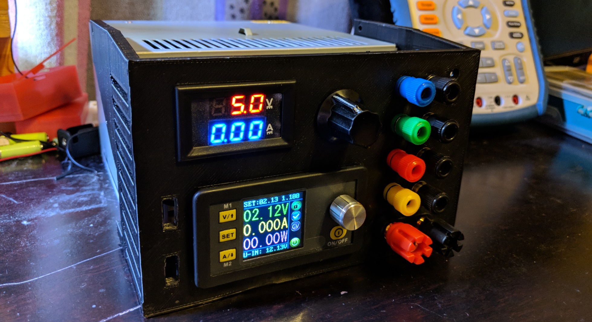
Goal of the project is to make a benchtop power supply from an ATX PC power supply. I started this project a few months ago and made a working protoyped (pictured). The intent was to have a 3.3V, 5V and a 12V rail with voltage and current sense, as well as a buck converted to drop the 12V to a user selectable voltage.
After using it for a short amount of time, I learned that this power supply has quite a bit of voltage drop even when pulling a small amount of current (<100mA). The resistance from the output of the ATX supply to the front face of the supply is very small (<0.3 Ohm),so I don’t think the drop is from that. I grabbed this power supply from an old PC, so I am thinking it is just poor load regulation or the low side current sense is created an undesired ground potential. Whatever the reason, it’s perfect opportunity to upgrade.
Key Upgrades
- uA current sense on the 3.3V
- Independent current sense
- On/Off for each power rail
- GUI with readouts for each power rail
The next major upgrade will be the display. I’m adding a 3.5” TFT LCD touchscreen, purchased from ebay for about $8 (Note: I do not recommend this display, as you get shipped an LCD with an unknown LCD driver. It was very difficult to get the Arduino to display anything on here. It took hours and hours of hunting down the correct library. Definitely worth the extra $20 for a known and reliable display)). Planned upgrades is for the display to autoscale the currents to uA, mA or A.
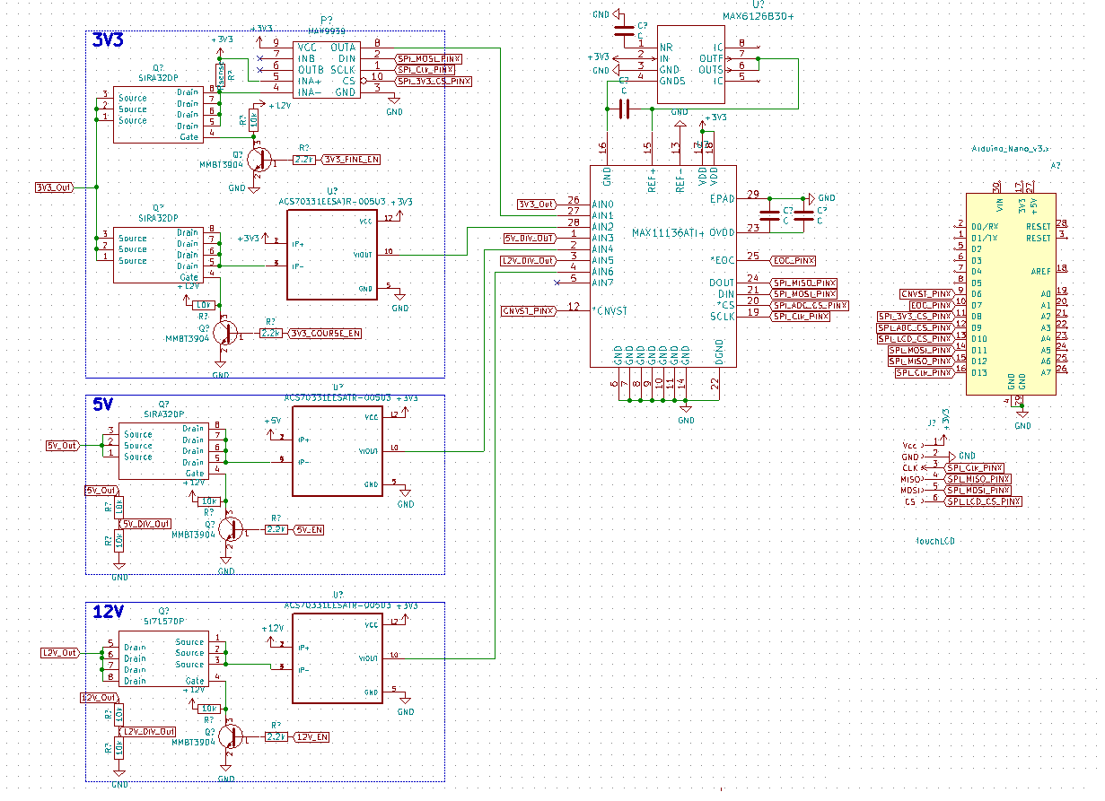
The heart of this design is the MAX11136, 8-Channel 12 bit 500ksps ADC with SPI. Not the fastest ADC, but perfect for measuring all the signals of interest in one package with an easy interface. The course current sense is done with an Allegro ASC70331, Hall-effect current sense. With a low resistance but high sensitivity, this will minimize any voltage drop with heavy loads but still have the resolution at lighter loads. For the finer current sense on the 3.3V rail the MAX9939 was chosen. It’s an SPI Programmable Gain Amplifier (PGA) that will allow for a high side current sense with a selectable range. This was put on a different power path than the course current sense to reduce the resistance at one time. MOSFETs were used to enable or disable each power rail controlled with the microcontroller.
The LCD communicates with the microcontroller with UART. A simple 1 character handshake was used to protect against dropouts. All data sent to the LCD is assumed to be “good”. Visually, one bad sample out of 100 will not be seen and it was deemed unnecessary for data integrity. Each rail will have an On/Off switch and the 3.3V will have an extra switch for a fine/course current sense resolution.
Below shows a schematic of the design with the MAX11136. A future version is currently in work that will eleminate this chip. A SAMD21G18A will be used instead.